Inductive sensor: contactless detection of metal objects approaching each other
An inductive sensor is used to determine the distance to a metal object. If the distance drops below a certain value (the so-called switch distance S), then the sensor will trigger an action. That is why it is indispensable as a tool in automation processes – e.g. as a guide for the grippers used in industrial machines. It can be used in a considerably larger range of application areas, however. For example, an inductive sensor can also monitor liquid levels with the help of metal floaters. This versatility makes it a valuable tool in all industrial areas as well as in a multitude of machines.
Table of contents
How does an inductive sensor work?
What is the difference between flush and non-flush sensors?
What kind of materials/conductive materials can an inductive sensor detect?
What is the difference between nominal switch distance (Sn) and real switch distance (Sr)?
Working with inductive sensors: the advantages and disadvantages at a glance
How does an inductive sensor work?
The following mnemonic helps to understand the functionality of an inductive sensor: The word “induction” comes from the Latin verb “inducere”, which means something like “guiding inside”. It registers a contact to an inserted object without touching it. The sensor has an active surface – an oscillator – on its front. This emits an electromagnetic field in a semicircle. A metal object being inserted in the field will weaken this field. This allows the sensor to detect how far away the object is – and act accordingly. Depending on the model, the measuring distance ranges from 0.5 to 50 millimetres.
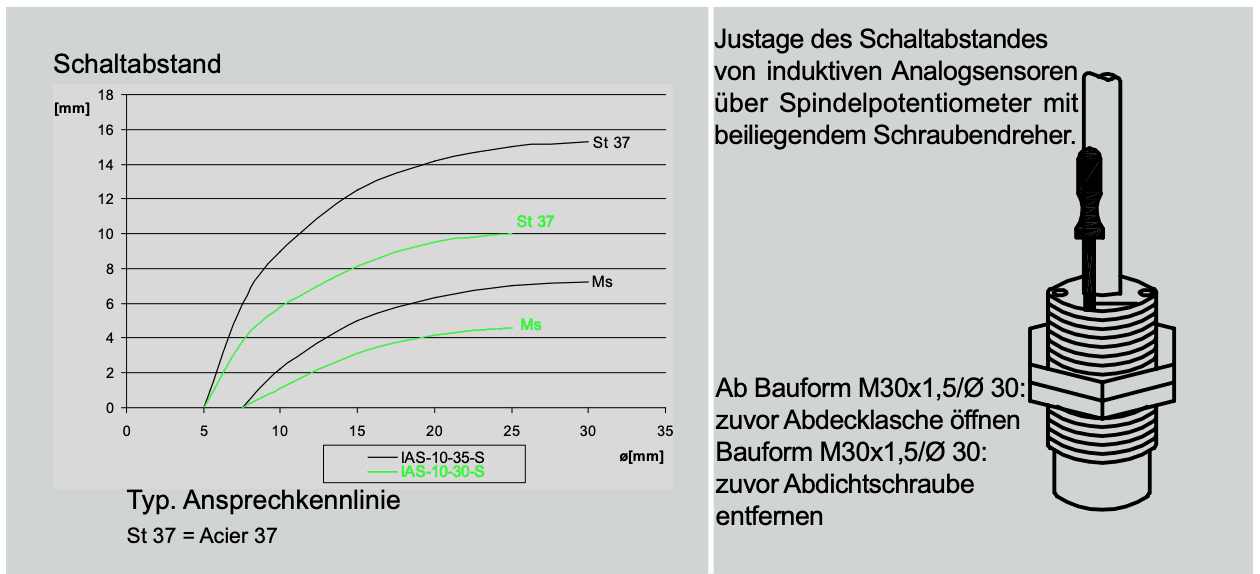
As an example in industrial automation: Steel generally has a nominal switch distance (Sn) of six millimetres. If a corresponding component drops below this distance, the sensor will trigger a movement of the gripper. The number of actions that an inductive sensor can trigger per second is called the switch frequency. Currently this value ranges from a few hundred to a thousand switches. The sensors are thus also suitable for fast production processes or real–time monitoring – for example in a gasoline tank.
What is the difference between flush and non-flush sensors?
The question really only comes up when an inductive sensor is to be installed in a metal environment. Flush models make it possible for the active surface to fit in with its environment. An outer metal ring shields the oscillation spool and thus prevents the adjoining metal from influencing the magnetic field. Non-flush sensors have no such ring. Accordingly, they may not be flush with the surrounding material. In general, they should have a so-called free zone (distance to the next metal) of at least triple the nominal switch distance.
What needs to be taken into account when inductive sensors are installed serially or across from each other?
When two flush inductive sensors are installed serially, the free zone between them should correspond to at least the diameter of the oscillation spools of the models. If the sensors are not flush, the free zone should amount to at least double of the nominal switch distance (2xSn).
If the sensors are directly across from each other, the risk of them mutually influencing each other are very large. That is why the distance between them should be at least eight times the nominal switch distance (8x Sn) – and more distance would be even better.
What kind of materials/conductive materials can an inductive sensor detect?
Currently, the sensors detect the following metals:
– Steel
– Cast iron
– Nickel
– Stainless steel
– Copper
– Aluminium
– Brass
What is the difference between nominal switch distance (Sn) and real switch distance (Sr)?
The nominal switch distance is measured under ideal conditions. The real switch distance calculates external factors, such as large temperature fluctuations. That is why it provides dependable values for daily use. Our models feature solid enclosures made of plastic or metal that are moulded with epoxy resin. They ensure that the effects of external influences remain controllable.

Working with inductive sensors: the advantages and disadvantages at a glance
Advantages:
– Contactless and thus low-wear
– High switching accuracy and high switch frequencies
– Resistant to dirt and soiling
– Resistant to vibrations and impacts
– Short circuit-proof
Disadvantages:
– Only metals can be detected
– The switch distance is so low that it is almost always necessary to install several sensors in a row
– Magnetic fields can lead to disruptions in measurement accuracy which can lead to disadvantages, for example, in some motor types (hybrid)
Other interesting articles
Capacitive sensor
Find out everything about the assembly and functionality of a capacitive sensor.
Capacitive filling level measurement
Find out everything about the process and functionality of capacitive filling level measurement.
Filling level sensor
Find out everything about the assembly and functionality of the filling level sensor.


